Fiber Optic Cable Connectors: 10 Essential Powerful Facts 2025
Why Fiber Optic Cable Connectors Are Critical for Network Performance
Fiber optic cable connectors are precision mechanical devices that join fiber optic cables together, enabling quick connection and disconnection while maintaining optimal light transmission. These connectors consist of three main components: a ceramic ferrule that holds the fiber, a connector body that houses the cable, and a coupling mechanism for secure attachment.
Key Types of Fiber Optic Cable Connectors:
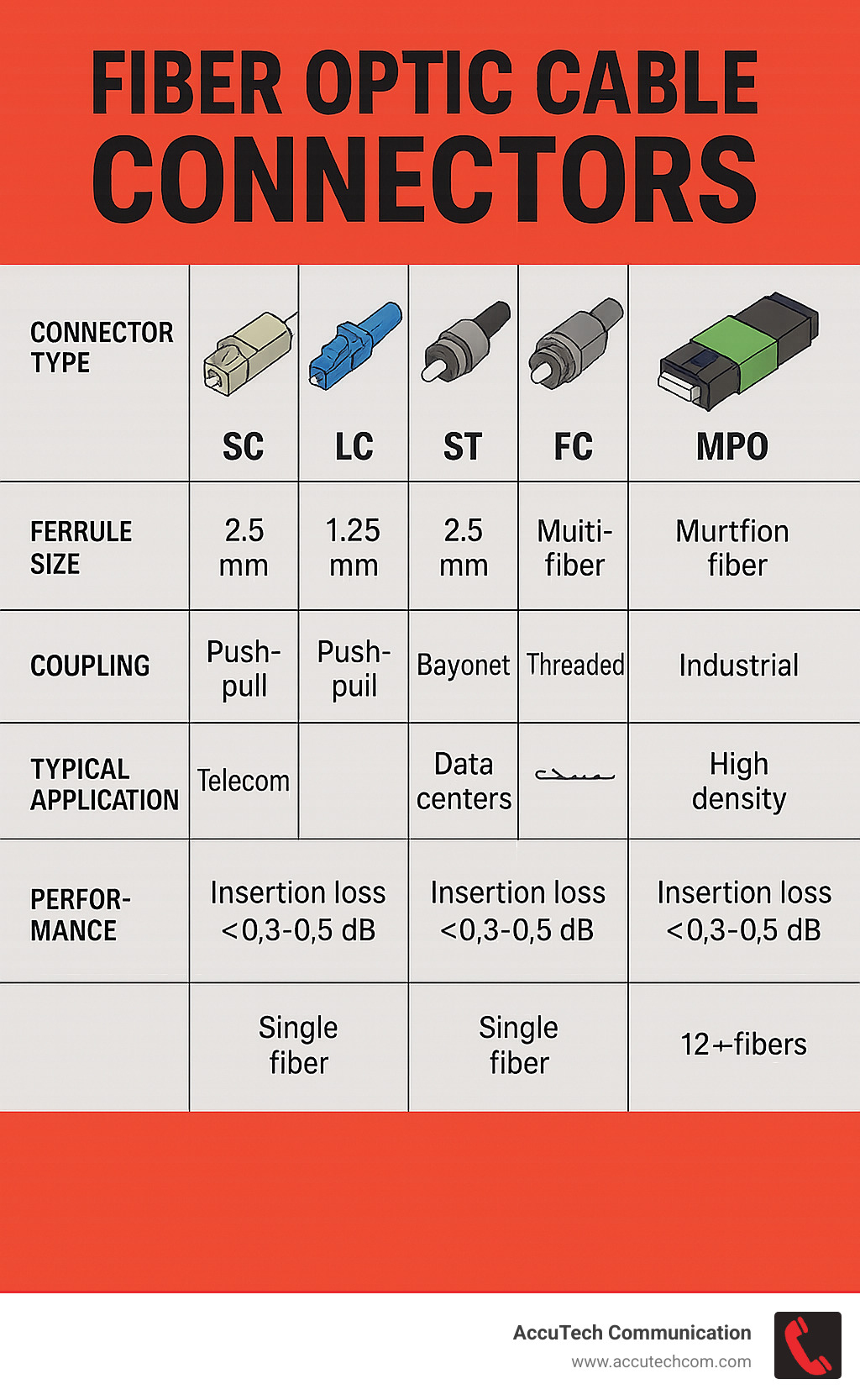
– SC (Subscriber Connector) – Push-pull design with 2.5mm ferrule, common in telecom
– LC (Lucent Connector) – Compact 1.25mm ferrule, ideal for high-density data centers
– ST (Straight Tip) – Bayonet twist-lock, legacy but still used in some applications
– FC (Ferrule Connector) – Threaded metal housing, excellent for vibration-prone environments
– MPO/MTP – Multi-fiber connectors supporting 12-144 fibers in a single housing
Unlike copper connections that carry electrical signals, fiber connectors must align microscopic glass fibers with extreme precision to transmit light pulses without significant loss. A qualified connector maintains insertion loss below 0.5 dB and return loss above 25 dB, ensuring your network operates at peak performance.
The choice of connector directly impacts your network’s reliability, scalability, and maintenance requirements. With over 80 connector styles developed but only a handful widely adopted, selecting the right type for your specific application is crucial for long-term success.
I’m Corin Dolan, owner of AccuTech Communications, and I’ve been installing and maintaining fiber optic cable connectors across Massachusetts, New Hampshire, and Rhode Island since 1993. My experience with healthcare, manufacturing, and enterprise networks has shown me how the right connector choice can make or break critical communications infrastructure.
Fiber optic cable connectors word roundup:
– how to terminate fiber optic cable
– types of fiber optic cable
– fiber optic technician
The Anatomy & Purpose of Fiber Optic Cable Connectors
Think of a fiber optic cable connector as the ultimate precision tool—it needs to align glass fibers thinner than human hair with the accuracy of a Swiss watchmaker. The tolerances we’re talking about are measured in micrometers, which is pretty incredible when you consider that these tiny components handle the data that keeps our modern world connected.
After three decades of installing these connectors across New England, I’ve developed a real appreciation for the engineering that goes into each one. Every fiber optic cable connector contains three essential parts that work together like a well-orchestrated team.
The ferrule is the star of the show. This small ceramic component—usually made from zirconia—holds the fiber in perfect alignment. The ferrule has a precisely drilled hole that’s just slightly larger than the fiber itself, typically around 124-127 micrometers for standard 125-micrometer fiber.
The connector body is the protector. This housing surrounds the cable jacket and those important strength members like aramid yarn that prevent the delicate glass from breaking under stress. When someone accidentally tugs on a cable, the connector body transfers that stress away from the glass core.
The coupling mechanism makes it all work reliably. Whether it’s a simple push-pull design, a bayonet twist, or threaded connection, this component ensures you get the same solid connection every single time.
The physics behind why this matters is fascinating. Light bounces through the fiber core thousands of times per meter, and any tiny gap or speck of dust at the connection point scatters that light signal. Even a microscopic air gap can cause about 0.3 dB of signal loss due to Fresnel reflection.
More info about How Do Fiber Optic Cables Work
Why Connectors Matter in Modern Networks
Loss budget management becomes critical when you’re planning network links. Each connector pair adds to your total signal loss, so keeping insertion loss under 0.5 dB per connector and return loss above 25 dB ensures your network performs reliably across longer distances.
Quick re-patching capability transforms how you manage network changes. Instead of scheduling lengthy maintenance windows, technicians can redirect traffic in minutes. We’ve helped clients reduce their network change windows from hours to just a few minutes.
Modularity for future growth means the infrastructure we install today can handle tomorrow’s faster speeds. The same physical connections that carry 1 Gigabit Ethernet today can support 10, 40, or even 100 Gigabit speeds later—you just swap out the transceivers.
Core Components Explained
The zirconia ferrule deserves special attention because it’s what makes modern fiber connectivity possible. This ceramic material is harder than steel and can be polished to an incredibly smooth finish—we’re talking surface roughness measured in nanometers.
Spring-loaded mechanisms inside the connector ensure consistent contact pressure between fiber end-faces. Keying systems prevent costly mistakes during installation by ensuring connectors can only be inserted in the correct orientation.
Types of Fiber Optic Cable Connectors – From SC to MPO
When I started AccuTech Communications back in 1993, the fiber optic cable connectors world was much simpler. Today, the evolution has been driven by one main factor: the relentless demand for more connections in less space.
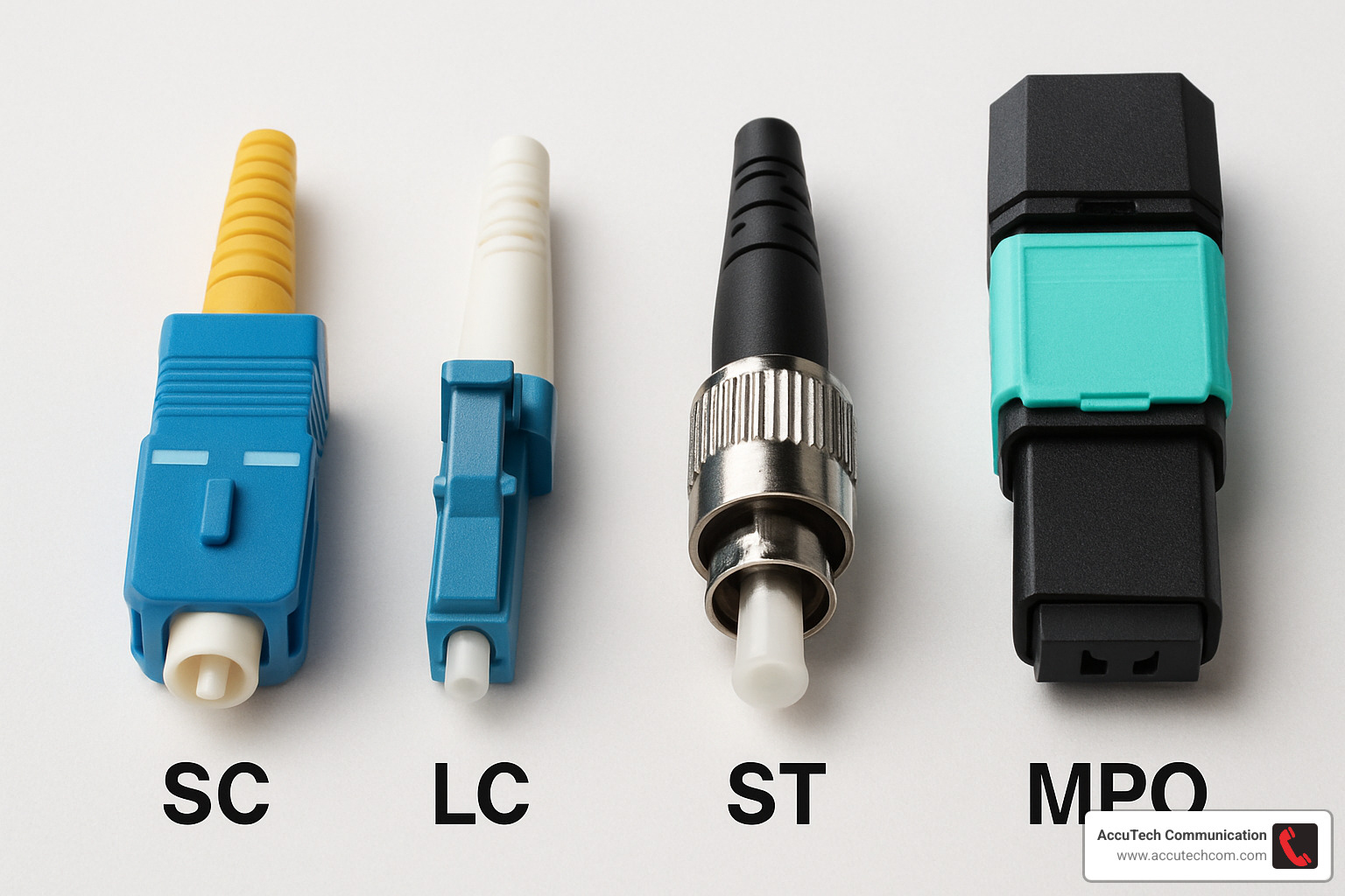
SC connectors were the workhorses of the early 2000s with their 2.5mm ferrule and reliable push-pull design. They’ve earned their place in telecommunications and cable TV applications.
LC connectors changed everything with their compact 1.25mm ferrule. Suddenly, we could fit twice as many connections in the same patch panel space. Data centers adopted them immediately.
ST connectors might seem old-fashioned with their bayonet twist mechanism, but they’re still reliable in industrial settings.
FC connectors bring serious durability with their threaded metal housing. When you need a connection that won’t budge under vibration, FC connectors are your friend.
MPO/MTP connectors are the heavy lifters, handling 12 to 144 fibers in a single housing. They’re essential for today’s high-speed networks where parallel optics rule.
| Connector Type | Ferrule Size | Coupling Method | Typical Loss | Fiber Count | Best Applications |
|---|---|---|---|---|---|
| SC | 2.5mm | Push-Pull | 0.25 dB | 1-2 | Telecom, CATV, Single-mode |
| LC | 1.25mm | Push-Pull Latch | 0.25 dB | 1-2 | Data Centers, High-density |
| ST | 2.5mm | Bayonet Twist | 0.25 dB | 1 | Legacy Networks, Multimode |
| FC | 2.5mm | Threaded | 0.25 dB | 1 | Test Equipment, Vibration-prone |
| MPO/MTP | Rectangular | Push-Pull | 0.35 dB | 12-144 | Backbone, Parallel Optics |
SC vs LC Fiber Optic Cable Connectors (2.5 mm vs 1.25 mm)
SC connectors are like the pickup truck of fiber connectors: reliable, proven, and perfect when you need something that just works. That 2.5mm ferrule provides excellent mechanical stability, and the push-pull mechanism works flawlessly even when you’re wearing thick gloves.
LC connectors are the sports car of the fiber world—sleek, efficient, and designed for performance. That 1.25mm ferrule might be half the size of SC, but it delivers the same excellent optical performance. In high-density applications, LC connectors are game-changers.
Color coding helps keep everything straight. Both SC and LC follow the same standards: blue for single-mode, beige or aqua for multimode, and green for APC polish.
ST & FC Legacy Options
ST connectors aren’t obsolete. That bayonet twist mechanism provides excellent retention, though it requires rotational access that can be tricky in tight spaces. They’re particularly common in manufacturing facilities with 15-20 year old installations.
FC connectors are built for precision applications where performance matters more than installation speed. The threaded coupling provides maximum security and vibration resistance. In paper mills, steel plants, and other heavy industrial environments, that threaded connection stays put when everything else is shaking.
MPO/MTP High-Density Fiber Optic Cable Connectors
MPO and MTP connectors can pack 12 to 144 fibers into a single connector housing. The alignment pin system ensures that all fibers align perfectly across the entire connector simultaneously.
Data centers have adopted MPO connectors for backbone applications. Modern switches with QSFP28 and QSFP-DD transceivers rely on MPO connectivity for parallel optics. We can run a single 12-fiber MPO trunk cable between floors, then break it out to 12 individual LC connections using fan-out assemblies.
Polarity management becomes critical with multi-fiber connectors. The industry has standardized three polarity methods—Type A, Type B, and Type C—that define how transmit fibers connect to receive fibers.
Scientific research on multi-fiber connectors continues to push the boundaries of what’s possible.
Choosing, Installing & Terminating the Right Connector
Picking the right fiber optic cable connectors starts with understanding your network’s needs today and tomorrow. After three decades of installations across New England, I’ve learned that the best connector choice starts with asking the right questions about your specific situation.
Application mapping means being smart about what you’re connecting. If your new Cisco switch has LC ports and you’re planning to use SC connectors, you’ve just created a mismatch that’ll require adapters or hybrid cables.
The single-mode versus multi-mode decision affects everything downstream. Single-mode applications typically need APC (angled physical contact) polish—that’s the green-colored connectors. Multi-mode setups usually work fine with UPC (ultra physical contact) polish.
Field-installable fast connectors can be installed in under a minute without epoxy, polishing, or curing time. They typically show insertion loss around 0.5 dB while cutting installation time dramatically.
Pre-terminated assemblies offer factory quality with field flexibility. We’re installing more factory-terminated trunk cables with breakout options for backbone runs.
More info about How to Terminate Fiber Optic Cable
Installation Methods & Tools
Epoxy-polish termination remains the gold standard when you need the absolute lowest loss numbers. This method consistently delivers insertion loss values between 0.1 and 0.3 dB but takes about 15 minutes per connector.
Crimp-polish methods cut out the epoxy mixing and curing steps while maintaining excellent performance. You still need to polish the end-face, but the overall process is faster and less messy.
Cleave-and-crimp technologies use a pre-polished ferrule with an internal mechanical splice. Strip the cable, cleave the fiber, insert it into the connector, and you’re done in about two minutes.
Fusion splice pigtails offer the ultimate performance approach. Instead of terminating connectors directly onto cables, we fusion splice factory-terminated pigtails to the cable fibers.
Cleaning & Maintenance Best Practices for Fiber Optic Cable Connectors
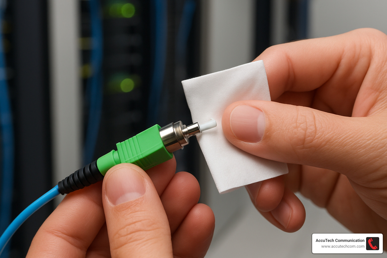
Contamination causes about 80% of the problems we’re called to fix. A speck of dust invisible to your naked eye can cause major signal loss or permanent damage to those precision-polished ceramic ferrules.
Lint-free cleaning materials aren’t optional—they’re essential. Regular tissues leave behind fibers and residue that create more problems than they solve.
Inspection before and after cleaning reveals contamination you’d never see otherwise. We inspect every connector before cleaning to see what we’re dealing with, then inspect again after cleaning.
One-click cleaners provide consistent results because they advance fresh cleaning material for each use. Mating dust caps are your first line of defense—every unused connector port should have a dust cap.
The cleaning sequence matters: always clean both sides before connecting, clean the adapter first, then the patch cable connectors. Use a gentle spiral motion from center outward.
Testing & Troubleshooting Connector Performance
Optical Loss Test Sets (OLTS) give you the fundamental measurement to verify connector performance. Optical Time Domain Reflectometry (OTDR) provides detailed analysis of connector behavior within complete fiber links.
Visible Fault Locators (VFL) help identify obvious problems like broken fibers or severely contaminated connections. Certification testing creates documentation for warranty and compliance purposes.
Common failure modes break down predictably: contamination causes about 70% of problems, damaged end-faces account for 20%, and incorrect connector types or polarity issues make up the remaining 10%.
Costs, Brands & Emerging Innovations
Understanding the financial side of fiber optic cable connectors helps you make smart decisions for your network infrastructure. The right connector choice can save thousands in long-term operational costs, even if the initial investment seems higher.
Basic connector costs start quite reasonably for standard applications. Field-installable fast connectors offer interesting cost equations—while the connector costs more, the labor savings can be substantial. We’ve reduced installation time from 10-15 minutes per connector to under two minutes.
Factory-terminated assemblies represent the premium option, delivering factory-quality performance with consistent results. Hardened HFOC connectors have revolutionized outdoor installations, withstanding salt air, temperature cycling, and mechanical stress.
The innovation pipeline continues delivering exciting developments. Low-loss nano-polish techniques now achieve insertion loss values below 0.1 dB. Connector-on-board optics eliminate traditional transceiver modules, reducing power consumption and enabling more compact equipment designs.
Push-pull mini-MPO connectors address space challenges in high-density installations while maintaining multi-fiber capability.
Latest research on connector trends
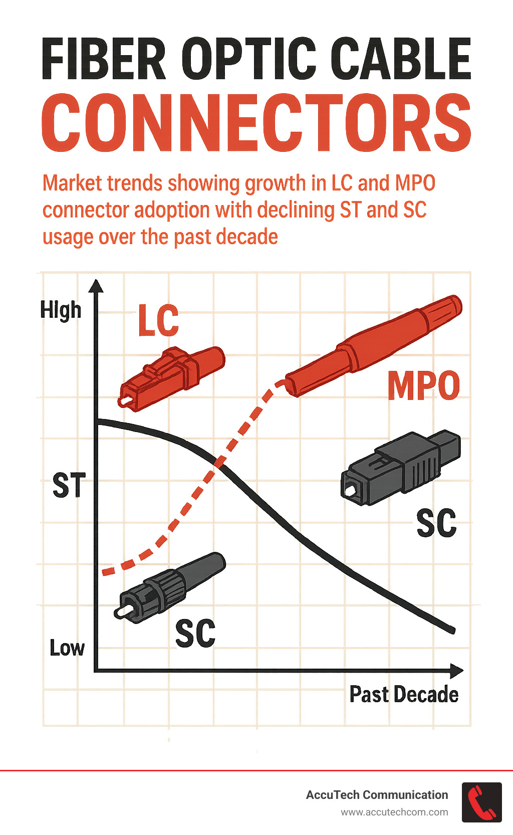
Market trends clearly favor higher density and better performance. LC connectors continue gaining market share due to their compact size, while MPO adoption accelerates with 40 Gigabit and 100 Gigabit Ethernet deployments.
Environmental considerations increasingly influence connector design. Manufacturers are developing recyclable materials and reducing packaging waste.
Future innovations will likely focus on supporting even higher data rates—400 Gigabit and 800 Gigabit Ethernet are already on the horizon. Fiber optic cable connectors must evolve to support parallel optics architectures while maintaining the reliability and ease of use that make fiber practical for everyday applications.
Frequently Asked Questions about Fiber Optic Cable Connectors
After three decades of installing fiber optic cable connectors across New England, these are the questions that come up most often during our consultations and service calls.
What’s the difference between APC and UPC connector polish?
The polish type on your fiber optic cable connectors makes a huge difference in performance, especially for single-mode applications.
UPC (Ultra Physical Contact) connectors feature a slightly domed end-face that’s polished to create physical contact between the fiber cores. These connectors typically achieve return loss values around 50-55 dB, which works great for most applications.
APC (Angled Physical Contact) connectors take things further with an 8-degree angled polish. This design redirects any reflected light into the fiber cladding instead of bouncing it back toward your equipment. The result? Return loss values exceeding 60 dB, critical for cable TV systems, long-distance telecommunications, and RF-over-fiber installations.
Here’s the important part: never mix APC and UPC connectors together. The industry uses color coding—UPC connectors have blue housings for single-mode or beige/aqua for multi-mode, while APC connectors always use green housings.
How many mating cycles can a connector withstand?
Most fiber optic cable connectors are rated for 500 to 1,000 mating cycles under laboratory conditions. But proper handling and maintenance matter far more than the theoretical rating.
In clean data center environments with good maintenance practices, we’ve seen connectors perform well beyond their rated cycles. The key factors are keeping them clean, avoiding side loads during insertion, and always using dust caps.
Degradation happens gradually through microscopic wear and contamination buildup. This is why we always clean both sides before making any connection—it preserves the connector’s lifespan.
Can I mix single-mode and multi-mode connectors in one link?
The short answer is absolutely not—never mix single-mode and multi-mode fibers in the same optical link, even if the connectors physically fit together.
The core sizes are completely different. Single-mode fiber has a tiny 9-micrometer core designed for laser light. Multi-mode fiber uses much larger 50 or 62.5-micrometer cores optimized for LED light sources. The fundamental mismatch causes severe signal loss.
Equipment damage is a real risk too. We’ve seen transceivers fail when connected to incompatible fiber types.
The color coding system exists for a reason. Single-mode fiber optic cable connectors use blue housings (UPC polish) or green housings (APC polish), while multi-mode connectors use beige or aqua. Always verify the fiber type before making connections.
Conclusion
Fiber optic cable connectors are the unsung heroes of modern network infrastructure. These precision-engineered devices might look simple from the outside, but they’re performing optical magic—aligning microscopic glass fibers with tolerances that would make a Swiss watchmaker proud. The connector choices you make today will echo through your network’s performance for decades to come.
After three decades of crawling through cable trays and troubleshooting connection problems across New England, I’ve learned that great fiber connectivity comes down to three fundamentals: choosing connectors that match your specific needs, following proven installation practices religiously, and never skipping the cleaning and testing steps (even when you’re running behind schedule).
The technology keeps getting better, which honestly amazes me. When we started AccuTech Communications in 1993, ST connectors were cutting-edge. Now we’re installing MPO connectors that pack 144 fibers into a housing smaller than those old ST connectors. The hardened environmental designs and ultra-low-loss polishing techniques available today would have seemed like science fiction back then.
What hasn’t changed is the importance of getting the basics right. Fiber optic cable connectors still demand respect—they’re precision instruments, not electrical plugs you can jam together and hope for the best. A speck of dust invisible to your naked eye can shut down a million-dollar network link. But when you treat them properly, they’ll deliver rock-solid performance that makes your entire infrastructure shine.
We’ve built AccuTech’s reputation on understanding that every connector matters, whether it’s a simple patch cable in a small office in Marlborough or a complex MPO backbone in a Worcester data center. Our clients trust us because we bring the same attention to detail to every connection, every time.
The modular flexibility that fiber optic cable connectors provide becomes more valuable as your network grows. Equipment changes, applications evolve, and speed requirements increase—but well-designed connector infrastructure adapts and endures. That’s the beauty of doing it right the first time.
More info about Fiber Optic Cabling
