How to Test Fiber Optic Cable: Top 5 Expert Tips in 2024
The Importance of Fiber Optic Testing: Ensuring Network Reliability and Minimizing Downtime
When it comes to establishing and maintaining a high-performance network, understanding how to test fiber optic cable effectively is crucial. Immediate steps to ensure your fiber optic cable is up to par include:
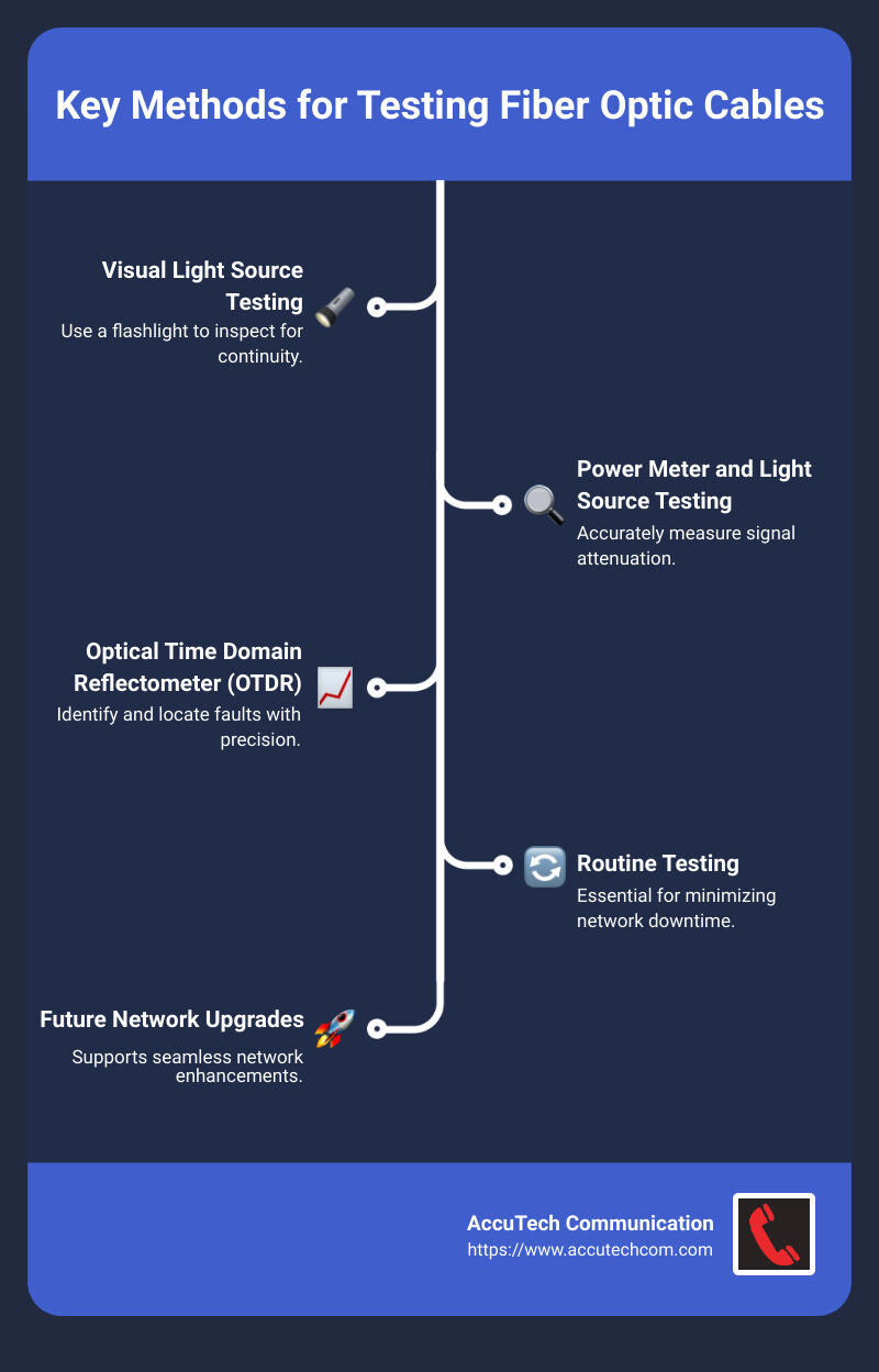
- Visible Light Source Testing: Use a flashlight to inspect for continuity.
- Power Meter and Light Source Testing: Accurately measure signal attenuation.
- Optical Time Domain Reflectometer (OTDR): Identify and locate faults with precision.
Testing fiber optic cables routinely is no trivial task. It plays an essential role in minimizing network downtime, ensuring the longevity of the network, and reducing maintenance needs. This comprehensive quality control translates into significant improvements in the network’s overall performance and reliability.
Network disruptions in fiber optic systems can be costly and inconvenient. According to recent data, around 50% of data centers face service outages annually. Ongoing fiber optic cable testing is essential to prevent such outages. Not only does it keep everything running smoothly, but it also supports future network upgrades.
I’m Corin Dolan, owner of AccuTech Communication with vast experience in how to test fiber optic cable. Our team ensures your business maintains top-notch communication networks across Massachusetts, New Hampshire, and Rhode Island.
Understanding Fiber Optic Cable Testing
Testing fiber optic cables is crucial for maintaining network reliability and performance. Let’s break down the types of tests, their importance, and some basic concepts.
Types of Tests
- Visible Light Source Test: This test uses a visible light source, like a visual fault locator, to check for continuity and detect breaks or faults in the fiber. It’s a simple yet effective way to ensure the cable is intact.
- Power Meter and Light Source Test: Known as the one-jumper method, this is the most accurate way to measure attenuation (signal loss) over a fiber optic cable. It involves a light source and a power meter to measure the amount of light lost between two points.
- Optical Time Domain Reflectometer (OTDR): This advanced test method uses an OTDR device to send a series of light pulses down the fiber. It measures the light reflected back to detect and locate faults, splices, and bends along the cable.
Importance of Testing
Regular testing of fiber optic cables offers several benefits:
- Minimizes Network Downtime: Early detection of faults prevents unexpected outages.
- Increases Longevity: Identifying issues early can extend the life of your fiber optic network.
- Reduces Maintenance Costs: Proactive testing reduces the need for costly emergency repairs.
- Supports Upgrades: Ensures the network is ready for future enhancements.
These factors contribute significantly to the long-term performance, manageability, and reliability of your fiber optic network.
Basic Concepts
Understanding the basics of fiber optic cables is essential for effective testing:
- Core: The center of the fiber cable, made of glass or plastic, where light transmission occurs.
- Cladding: Surrounds the core and reflects light back into it, enabling the light to travel down the fiber.
- Coating: The outer layer that protects the core and cladding from damage.
Types of Fiber
- Multimode Fiber: Has a larger core diameter, allowing multiple light modes to pass through. It’s easier to connect but has higher attenuation and is suitable for shorter distances.
- Single-mode Fiber: Features a smaller core diameter, allowing only one mode of light to pass through. It offers higher performance over longer distances but requires more precise alignment and expensive equipment.
Practical Insights
When testing fiber optic cables, it’s important to follow specific procedures. For instance:
- Visible Light Source Test: Connect a fiber optic flashlight to one end of the cable and check for visible light at the other end. If no light is visible, there may be a break or fault.

- Power Meter and Light Source Test: Use a calibrated power meter and light source to measure the light loss over the cable. Compare the results with the TIA/EIA standards to ensure compliance.
By understanding these basic concepts and the importance of testing, you can effectively maintain and troubleshoot your fiber optic network. Next, we’ll dive deeper into specific testing methods, starting with how to test fiber optic cable using a visible light source.
How to Test Fiber Optic Cable Using a Visible Light Source
Testing fiber optic cables is crucial for ensuring network reliability. One of the simplest methods to test fiber optic cable is by using a visible light source. This technique helps identify breaks and continuity issues in the cable. Let’s explore how this works.
Visual Fault Locators
Visual Fault Locators (VFLs) are devices that emit a bright, visible laser light. They are invaluable for continuity checks and troubleshooting. When connected to a fiber optic cable, the VFL sends light through the cable. If there’s a break, the light will escape at the fault point, making it easy to spot.
Continuity Checks
Continuity checks verify that the light can travel from one end of the cable to the other without interruption. Here’s how to perform a continuity check using a visible light source:
- Connect the VFL: Attach the VFL to one end of the fiber optic cable.
- Inspect the Other End: Look at the opposite end of the cable. If you see the light, the cable is continuous. If not, there’s a break.
- Identify Faults: If there’s a break, you can often see the red glow at the fault point along the cable.
Safety Precautions
While using a VFL is straightforward, safety is paramount. The laser light can be harmful to the eyes. Here are some safety tips:
- Never Look Directly: Do not look directly into the active fiber optic strand.
- Use Safety Goggles: For higher power VFLs (above 5mW), always wear safety goggles.
- Proper Signage: Ensure appropriate warning signs are in place when using laser devices.
Documenting Results
After testing, document the results for each segment of the fiber optic cable. This practice helps in maintaining a record and aids in future troubleshooting.
By following these steps, you can effectively use a visible light source to test your fiber optic cables. This method is quick, simple, and provides immediate feedback on the cable’s integrity.
Next, let’s explore another essential testing method: using a power meter and light source.
How to Test Fiber Optic Cable with a Power Meter and Light Source
Testing fiber optic cables with a power meter and light source is crucial for ensuring accurate attenuation measurements. This method is more precise than using a visible light source and is essential for maintaining network performance.
One Jumper Method
The One Jumper Method is a straightforward approach for testing fiber optic cables. Here’s a step-by-step guide:
- Disconnect Active Equipment: Ensure no active equipment is connected to avoid interference.
- Calibrate Your Equipment: Follow the manufacturer’s instructions to calibrate the light source and power meter. Calibration ensures that your readings are accurate.
- Set the Correct Wavelength: Use a light source suitable for your fiber type:
- Single-mode fiber: 1310 nm or 1550 nm
- Multimode fiber: 850 nm or 1300 nm
- Connect Test Jumpers: Use the correct size test jumpers and couplers provided in your testing kit.
- Connect the first jumper to the optical source and the power meter.
- Turn on the unit and record the reference power reading (Pref) in dBm.
- Verify Attenuation: Insert a second test jumper using an adapter between the first jumper and the power meter. Ensure the added attenuation is not greater than 0.75 dB.
- Test the Fiber Cable:
- Disconnect the jumpers at the adapter.
- Connect the optical source/test jumper 1 to one end of the fiber optic cable being tested.
- Connect the power meter/test jumper 2 to the other end.
- Record Test Power Reading: Document the test power reading (Ptest) displayed on the power meter.
- Calculate Attenuation: Subtract Ptest from Pref to get the end-to-end attenuation:
Attenuation (dB) = Pref – Ptest
- Document Results: Keep a record of the end-to-end results for future reference and troubleshooting.
Accurate Measurement and Standards
Accurate measurement is key to ensuring network reliability. The TIA/EIA Standards provide guidelines for fiber optic testing:
- TIA/EIA-568: Specifies requirements for commercial building telecommunications cabling.
- TIA/EIA-526: Outlines methods for optical power loss measurements.
Following these standards ensures your testing is consistent and meets industry benchmarks.
Calibration
Always calibrate your equipment before each test. This step is critical for obtaining accurate results. Calibration involves setting the reference power level and ensuring the light source and power meter are aligned correctly.
By following these steps, you can accurately measure the attenuation of your fiber optic cables using a power meter and light source. This method is essential for maintaining network performance and reliability.
Next, let’s delve into advanced testing techniques using an OTDR.
Advanced Testing Techniques: Using an OTDR
An Optical Time-Domain Reflectometer (OTDR) is a powerful tool for fiber optic testing. It helps identify and locate faults along the length of a fiber optic cable. Let’s break down how it works and how to interpret its results.
OTDR Functionality
An OTDR sends a series of light pulses down the fiber optic cable. It then measures the light that is scattered or reflected back to the device. The time it takes for the light to return helps determine the location of any faults or imperfections in the cable.
Think of it as a radar system for your fiber optic network. It maps out the entire length of the cable, showing you where issues might be.
Graph Interpretation
The OTDR generates a graph called a trace. This graph shows the strength of the returned light over time. Here’s how to read it:
- Launch Event: This is the initial spike on the graph. It represents the point where the light enters the fiber.
- Splices and Connectors: These appear as small dips or spikes. They indicate where two fiber segments are joined or where connectors are used.
- Faults: Significant drops in the graph can indicate breaks or severe bends in the fiber.
Understanding this graph is crucial for pinpointing issues. For example, a sudden drop followed by a flat line usually means a break in the fiber.
Event Identification
Identifying events along the fiber is essential for effective troubleshooting. Here are common events you might see:
- Reflective Events: These are spikes caused by connectors or mechanical splices. They reflect more light back to the OTDR.
- Non-Reflective Events: These appear as dips and are usually caused by fusion splices or bends in the fiber.
- End of Fiber: The point where the trace drops to the baseline and remains flat. This indicates the end of the fiber.
Using an OTDR allows you to not only find faults but also understand the nature of these faults. This can save you significant time and money in troubleshooting and repairs.
By mastering the use of an OTDR, you can ensure your fiber optic network runs smoothly and efficiently. Next, we’ll explore common problems and solutions in fiber optic testing.
Common Problems and Solutions in Fiber Optic Testing
When testing fiber optic cables, you may encounter several common problems. Understanding and solving these issues is crucial for maintaining a reliable network. Here are some key areas to focus on:
Connector Issues
Dirty or Damaged Connectors:
A single particle on the fiber end-face can cause significant insertion loss and back reflection. Always inspect connectors using a fiber microscope before making any connections.
Solution: Use a fiber optic cleaning kit to ensure connectors are clean and free of debris. Inspect the connectors’ fiber ends to ensure they are smoothly polished.
Attenuation Problems
High Optical Loss:
As light travels through the fiber, it loses power. This loss, known as attenuation, can degrade signal quality. High attenuation can be caused by bends, poor splices, or faulty connectors.
Solution: Perform an insertion loss test using a power meter and light source. This will help you measure the optical loss and identify problem areas. For long distances, consider using an OTDR to pinpoint the exact location of high loss.
Troubleshooting Tips
Visual Fault Locator (VFL):
A VFL sends a visible red laser light through the fiber. If there are breaks or defects, the light will be visible through the coating.
Tip: Use a VFL to quickly identify breaks or macro-bends in the fiber. This is especially useful for short runs and patch cables.
Fiber Identifier (FI):
An FI can detect optical signals from the outside of the fiber. It helps confirm the presence of traffic and the direction of transmission.
Tip: Use an FI to verify the correct routing of fibers in complex installations.
End-Face Inspection:
A pristine end-face is essential for maintaining low loss and high performance. Even minor contamination can cause significant issues.
Tip: Regularly inspect and clean fiber end-faces to prevent insertion loss and back reflection. Use a fiber microscope for detailed inspection.
By addressing these common problems and using the right tools, you can ensure your fiber optic network performs optimally. Next, we’ll discuss how to choose the right tools for testing fiber optic cables.
How to Choose the Right Tools for Testing Fiber Optic Cables
Selecting the right tools for testing fiber optic cables is crucial for ensuring network reliability and performance. Let’s break down the essential tools you’ll need: OTDR, Light Sources, Power Meters, and Visual Fault Locators.
OTDR (Optical Time-Domain Reflectometer)
An OTDR is a powerful tool that helps you detect, locate, and measure events along a fiber link. It provides a detailed view of the fiber’s characteristics, showing events like splices, connectors, and breaks.
Why use an OTDR?
– Detailed Analysis: Detects and measures loss and reflection events.
– Documentation: Provides a permanent record of fiber characteristics.
– Versatility: Suitable for both long and short fiber runs, although it excels in longer distances.
Pro Tip: Use launch and receive cables to qualify the front-end and far-end connectors. This ensures accurate measurements.
Light Sources
An Optical Light Source (OLS) is used in conjunction with a power meter to quantify the insertion loss of a fiber link. It’s essential for ensuring the optical power budget is within design specifications.
Why use a Light Source?
– Calibration: Helps in accurate measurement of signal loss.
– Compatibility: Works with various wavelengths to match the fiber under test.
Pro Tip: Always use a calibrated light source to ensure the accuracy of your measurements.
Power Meters
A Power Meter measures the optical power in a fiber link. When used with a light source, it helps in determining the end-to-end signal loss, known as attenuation.
Why use a Power Meter?
– Precision: Measures the exact amount of optical power.
– Attenuation Testing: Essential for verifying that the link meets TIA/EIA standards.
Pro Tip: Regularly calibrate your power meter to maintain accuracy. Compare your test results with the link attenuation allowance using the formula provided in the TIA/EIA standards.
Visual Fault Locators (VFL)
A Visual Fault Locator (VFL) is a simple yet effective tool for checking fiber continuity and identifying breaks or bends in the fiber.
Why use a VFL?
– Quick Troubleshooting: Easily identifies breaks and bends by emitting a visible red light.
– Safety: Ensure you never look directly at the VFL light to avoid eye damage.
Pro Tip: Use a VFL for quick checks on patch cords and to visually locate faults along the fiber.
By choosing the right tools for testing fiber optic cables, you can ensure accurate diagnostics and maintain optimal network performance. Next, we’ll dive into some frequently asked questions about fiber optic testing.
Frequently Asked Questions about Fiber Optic Testing
Can you test fiber with a flashlight?
Yes, but it’s not the best method.
Using a flashlight to test fiber optic cables is a very basic way to check continuity, but it comes with limitations. A flashlight can help you see if light passes through a fiber, which might indicate that the fiber is not completely broken. However, it’s not precise and won’t tell you much about the quality of the signal or pinpoint small issues.
Here’s why:
– Limited Light Coupling: Flashlights don’t focus light well into the tiny core of the fiber.
– Poor Sensitivity: Small bends or minor breaks might not be detected.
– Safety: Flashlights are safe for your eyes, unlike more powerful laser sources.
For more accurate and reliable testing, a Visual Fault Locator (VFL) is recommended. VFLs use a laser light that easily identifies breaks and bends in the fiber.
How do I test my fiber optic internet?
Testing your fiber optic internet involves a few steps to ensure everything is working correctly:
- Visual Inspection: Check the physical condition of the fiber and connectors.
- Use a VFL: This tool emits a red laser light to detect breaks or bends.
- Power Meter and Light Source: Measure the signal strength and loss across the fiber link.
- OTDR Testing: For detailed analysis, use an Optical Time-Domain Reflectometer (OTDR) to map the fiber and identify any faults.
Steps to test with a Power Meter and Light Source:
– Connect the Light Source to one end of the fiber.
– Attach the Power Meter to the other end.
– Measure the Signal: Compare the measured power with the expected values to determine if there’s any significant loss.
Pro Tip: Always ensure your equipment is calibrated and your connectors are clean for accurate results.
What indicates a bad fiber optic cable?
Several signs can indicate a bad fiber optic cable:
- No Light Transmission: If no light passes through the cable during a continuity test, it’s likely broken.
- High Attenuation: Excessive signal loss measured by a power meter can indicate problems.
- Visible Damage: Cracks, bends, or damaged connectors can impair performance.
- Error Messages: Network devices might show error messages or reduced performance.
Common Problems and Solutions:
– Connector Issues: Dirty or damaged connectors can cause high loss. Clean or replace connectors as needed.
– Bends and Kinks: Excessive bending can break the fiber. Ensure proper cable management to avoid sharp bends.
– Attenuation Problems: Use an OTDR to locate and measure loss events along the fiber.
Pro Tip: Regular maintenance and testing can help identify problems early and keep your network running smoothly.
By understanding these common issues and how to address them, you can ensure your fiber optic network remains reliable and efficient.
Conclusion
In summary, testing fiber optic cables is crucial for ensuring long-term network performance. Regular testing helps to minimize downtime, extend the network’s lifespan, and reduce maintenance needs. By following a structured approach to fiber optic testing, you can gain a comprehensive understanding of both the theoretical and practical aspects of maintaining and troubleshooting fiber optic networks.
AccuTech Communications has been a beacon of excellence in the business communications sector since 1993, providing top-notch fiber optic solutions. Our team of skilled technicians and engineers ensures that your network infrastructure is optimized for peak performance. From fiber optic cabling installation to ongoing maintenance and support, we have the expertise to keep your network running smoothly.
By implementing the testing techniques and best practices outlined in this guide, you can ensure optimal network performance and reliability. Whether you’re using a visible light source, power meter and light source, or an OTDR, understanding how to test fiber optic cables effectively will empower you to maintain and troubleshoot your network with confidence.
Ready to elevate your network’s performance? Contact AccuTech Communications today to learn more about our fiber optic solutions and how we can help you achieve a more reliable and efficient network.
