Fiber Optic Acceptance Testing Checklist: What to Review Before Handoff
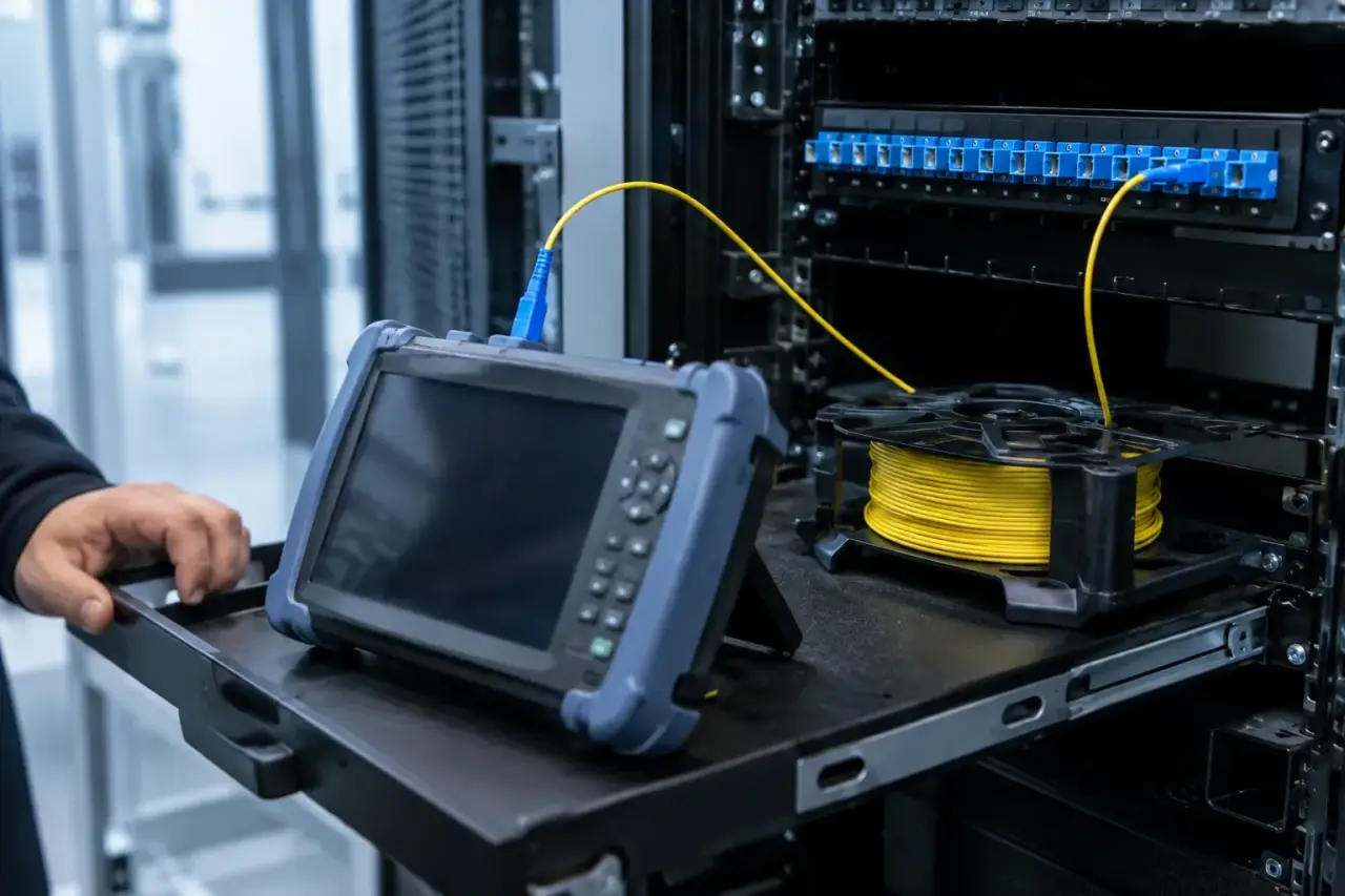
Fiber optic acceptance testing is the owner’s check that installed links, test records, labels, and closeout documents describe the same finished system. A folder of “pass” reports is not enough when the link names cannot be matched to patch-panel ports or the test method is not the one required by the project.
This checklist is written for facility, IT, and project teams reviewing a contractor’s handoff package. It does not replace a project-specific test plan or tell a technician how to operate an instrument.
Quick answer: Before acceptance, reconcile every required link to a final test record, confirm the method and limit came from the approved test plan, resolve exceptions, and retain the native records with the as-built link map.
Start with the approved acceptance basis
The acceptance basis should already be defined in the project documents. Gather the issued fiber schedule, route or riser drawing, approved product information, connector and enclosure schedule, test plan, loss budget or other project limit, change log, and required closeout format.
Do not substitute a generic internet threshold for a missing project requirement. Link length, fiber type, connector count, splice count, wavelength, test configuration, application, and referenced standard can all affect how a result should be evaluated. If the acceptance basis is unclear, document the gap and return it to the responsible designer, owner representative, or contractor for resolution before signoff.
Require one stable identity for every fiber link
Each installed link should have an identifier that appears consistently on the patch-panel or enclosure label, link schedule, as-built drawing, test filename, and report header. Reconciliation is the first owner-level control: it proves that a result belongs to the physical link being accepted.
A practical link register includes:
- Origin and destination telecom spaces
- Enclosure, panel, cassette, port, or strand position at both ends
- Fiber type, strand count, and connector interface
- Expected route or measured length, as defined by the project
- Required test method, wavelength, direction, and project limit
- Final result status and the location of the native record
If a result is named “Fiber 12” but the building has multiple panels with a port 12, the record is not sufficiently traceable. Resolve the naming ambiguity before treating it as accepted evidence.
Review the acceptance package by question, not file count
| Owner question | Evidence to review | Hold point |
|---|---|---|
| Was every required link tested? | Link register matched to native test files and readable reports | Missing, duplicate, or unmatched link IDs |
| Was the specified method used? | Test setup, wavelength, direction, reference method, and instrument record | Method differs from the approved test plan |
| Was the correct limit applied? | Approved project limit or loss budget associated with each link type | Generic, missing, or undocumented limit |
| Are events and route details consistent? | As-built route, splice and connector schedule, and OTDR record when specified | Unexpected event, length conflict, or undocumented route change |
| Were exceptions closed? | Issue log, corrective action, retest record, and approved disposition | Open exception or overwritten history |
Understand what the selected test method proves
The Fiber Optic Association explains that insertion-loss testing evaluates loss across the installed cable plant, while OTDR testing characterizes the link and its events. Its basic fiber optic testing reference also emphasizes documenting the cable plant so results can be interpreted against what was installed.
These records answer related but different questions. An optical loss test can show the end-to-end loss under the specified reference method. An OTDR trace can help locate and characterize connections, splices, bends, breaks, and route length. Where both are specified, one should not be silently substituted for the other. Fluke Networks similarly describes OLTS and OTDR as a complete testing strategy with complementary roles.
For acceptance, confirm that the instrument setup shown in the record matches the approved plan. Review the tested wavelength, direction, reference configuration, link identifier, limit, and result. When bidirectional testing is required, verify that both directions are present and correctly associated with the same link.
Reconcile results to the expected link construction
A report should make sense when compared with the as-built system. Review whether the recorded length is reasonably consistent with the route, whether the number and location of reported events align with planned connectors and splices, and whether any field change appears in both the drawing and link register.
A discrepancy is a question to resolve, not automatic proof of defective work. For example, a length conflict could reflect a mislabeled result, a revised pathway, an incorrect launch setup, or an inaccurate drawing. Record the discrepancy, identify the governing document, and obtain a corrected record or approved explanation.
Check records for traceability and completeness
Review a sample of records in depth and then reconcile the complete register. At minimum, look for:
- A unique link identifier that matches both ends of the installed link
- Test date and instrument identification
- Fiber type, wavelength, direction, and method required by the plan
- Measured value, applied limit, margin or result status where the instrument reports it
- Reference-cord or launch/receive configuration when relevant to the method
- Native test files in addition to static screenshots or PDFs
Native records matter because they preserve structured data and trace detail that may not be visible in a summary image. Keep a readable export as well so the owner can review the package without depending on a particular desktop application for every question.
Use an exception log instead of replacing failed history
When a link does not meet the approved criterion, create an exception entry tied to the link ID. Record the observed issue, investigation, corrective action, retest date, new record name, and final disposition. Do not simply overwrite the original evidence or rename the retest so the history disappears.
The exception workflow should distinguish between a corrected installation, a corrected record, an approved design change, and an unresolved issue. Acceptance can then be limited to the links with complete evidence while open items remain visible.
Inspect the physical handoff as well as the reports
A report review should be paired with a physical closeout walkthrough. Confirm that enclosures are secured, adapters and unused positions are protected, routing and bend management are orderly, labels are legible, and patching matches the final schedule. Check that work areas are clean and that owner-furnished keys, accessories, and records are delivered as required by the project.
If the project began with a fiber optic site survey, compare its pathway and telecom-space assumptions with the final as-built route. Capture approved field changes instead of leaving them only in email or meeting notes.
Assemble a maintainable fiber closeout package
Organize the final package so another technician can find a record from a label in the field. A useful folder structure groups documents by site, building, telecom space, cable segment, or another hierarchy that mirrors the link naming convention.
- Final link and strand register
- As-built route and enclosure drawings
- Native loss-test and OTDR files required by the plan
- Readable summary reports
- Closed exception log and corrective-action evidence
- Approved product substitutions and field changes
- Signoff record showing who reviewed each acceptance item
Retain the original file names and export settings. If records are consolidated, keep a cross-reference to the installer’s original link IDs so later troubleshooting does not depend on memory.
Use a final owner signoff checklist
Before signoff, verify that the link count matches the approved scope, every required record maps to a physical link, test methods and limits match the plan, exceptions are closed or explicitly reserved, labels match the documents, and the complete package is stored in an owner-controlled location.
Accutech’s fiber optic cabling installation page describes the established service this handoff guide supports. For a commercial fiber project in Massachusetts, New Hampshire, or Rhode Island, request an estimate and include the available route drawings, link schedule, test plan, and closeout requirements.


