How to Start IP Camera Wiring in Less Than an Hour
What You Need to Know Before Starting IP Camera Wiring
IP camera wiring is the process of connecting network-based security cameras to a recorder or switch using Ethernet cables, and doing it right is what separates a reliable surveillance system from one that fails when you need it most.
Here is a quick overview of how it works:
- Choose your cable: Cat5e, Cat6, or Cat6a Ethernet cable (Cat6a recommended for new commercial installations)
- Plan your runs, map cable paths from each camera location back to your PoE switch or NVR
- Route and conceal, run cables through walls, ceilings, or conduit depending on the environment
- Terminate with RJ45 connectors, using the T568B wiring standard on both ends
- Connect to a PoE switch, which delivers both power and data over a single cable
- Test every run, verify continuity and data transmission before finalizing the install
The result: a clean, high-performance IP camera system running over structured Ethernet cabling.
Getting this right matters more than most people realize. A single wiring mistake, a wrong crimp, an overlong cable run, or an unsealed outdoor connector, can take an entire camera offline. For commercial facilities in Massachusetts, New Hampshire, and Rhode Island, that is not a risk worth taking.
The good news? With the right cable, the right tools, and a clear plan, most of the work is straightforward.
I’m Corin Dolan, owner of AccuTech Communications, and I’ve spent decades designing and installing structured cabling systems, including IP camera wiring, for commercial clients across the region. In this guide, I’ll walk you through everything you need to get it done correctly the first time.
IP camera wiring terms explained:
Understanding the Basics of IP Camera Wiring
When deploying modern CCTV Security Systems for Business, the foundation of the entire system lies in its physical network cabling. Unlike legacy analog systems that rely on heavy coaxial cables, modern IP (Internet Protocol) cameras transmit video as a digital data stream. This digital approach allows for incredibly high resolutions, often exceeding 5 megapixels, along with advanced features like digital zoom and smart analytics.
For a deeper dive into how this compares to older setups, you can read more in this Security Camera Wiring: Ultimate Installation Guide 2026 .
At its core, IP camera wiring relies on twisted-pair copper Ethernet cables. These cables contain eight insulated copper wires wound together in four pairs. This twisting is not just for flexibility; it is a precise engineering method designed to cancel out electromagnetic interference and crosstalk from adjacent wires, ensuring that high-bandwidth video signals travel from the camera to your recording server without degradation.
Choosing the Right Ethernet Cable for IP Camera Wiring
Selecting the correct cable category is critical for the longevity and performance of your commercial surveillance system. The most common choices are Cat5e, Cat6, and Cat6a. While all of these can technically run IP cameras, they offer different levels of performance, bandwidth, and future-proofing.
- Cat5e: Released to reduce crosstalk compared to standard Cat5, Cat5e supports a bandwidth of 100 MHz and speeds up to 1 Gbps. It remains a cost-effective option for standard commercial installations. You can explore more details on Cat5e Cable specifications to see if it fits your project.
- Cat6: Operating at a bandwidth of 250 MHz, Cat6 supports 10 Gbps speeds over shorter distances. However, unshielded Cat6 cable has a maximum distance limit of 55 meters (180 feet) when running at peak bandwidth, after which it behaves similarly to Cat5e.
- Cat6a: The robust standard for modern commercial facilities. Cat6a supports 10 Gbps speeds up to a full 100 meters (328 feet) and features superior shielding and thermal properties. This makes it the ideal choice for high-power Power over Ethernet (PoE) applications. Learn more about deploying Cat6a Ethernet Cable 1000 ft spools for large-scale projects.
To help you compare, here is a quick breakdown of how these cables perform:
| Cable Type | Max Bandwidth | Max Speed (up to 100m) | PoE Suitability | Recommended Use Case |
|---|---|---|---|---|
| Cat5e | 100 MHz | 1 Gbps | Standard PoE (802.3af/at) | Budget-conscious legacy commercial upgrades |
| Cat6 | 250 MHz | 1 Gbps (10 Gbps < 55m) | Standard PoE+ | Mid-tier office networks and standard IP cameras |
| Cat6a | 500 MHz | 10 Gbps | High-Power PoE++ (up to 100W) | Future-proof commercial installations and PTZ cameras |
Power over Ethernet (PoE) and How It Simplifies Installation
In the early days of IP surveillance, cameras required two cables: one for data transmission and a separate electrical line for power. Power over Ethernet (PoE) completely revolutionized this by injecting low-voltage DC power directly into the unused twisted pairs of a standard Ethernet cable.
This means a single Cat5e or Cat6a cable delivers both high-definition video data and electrical power to the camera. It eliminates the need to hire an electrician to run high-voltage AC outlets near every camera location, saving significant installation time and cost.
To implement PoE, you will typically use one of two devices:
- PoE Switch: A network switch with built-in power injection. It connects to your network and powers multiple cameras directly from its ports.
- PoE Injector: A single-port device used when you only need to power one or two cameras and your existing network switch does not support PoE.
PoE operates on standard low-voltage limits (typically under 90 volts), making it incredibly safe to handle during installation. However, managing power budgets across a 16-port or 24-port switch requires careful planning. For troubleshooting power delivery, tools like a network tester with a PoE finder are invaluable. You can read more about how these tools work in our guide on Demystifying PoE: What a Network Cable Tester with PoE Finder Can Do for You.
Planning and Routing Your Commercial Camera Cables
Before drilling any holes or pulling cables from their spools, a comprehensive routing plan must be established. In a commercial setting, keeping your cables organized, protected, and compliant with local building codes is paramount.
Proper planning prevents the common nightmare of tangled lines, signal interference, and code violations. If you are budgeting for a professional commercial installation, keep in mind that average commercial camera installation costs can range widely depending on the size of the facility and the complexity of the routing. Based on publicly available internet data, commercial cabling and hardware installations typically range from $1,500 to $15,000+. Please note that these are average industry costs sourced from public data and do not reflect the actual rates of AccuTech Communications.
When routing cables, we must ensure they are kept at least 6 inches away from high-voltage electrical lines to prevent electromagnetic interference from ruining the video signal. Additionally, routing through dedicated pathways like PVC or metal conduit protects your investment from physical damage and tampering. For a complete look at using conduit, consult our Network Cable PVC Conduit Complete Guide.
Running and Concealing Cables Through Walls and Ceilings
For indoor installations, the most common routing path is through drop ceilings and hollow drywall. This keeps the low-voltage wiring completely hidden from view and protected from environmental hazards.
When running cables through ceiling spaces used for environmental air circulation (known as plenum spaces), building codes strictly require the use of plenum-rated (CMP) cabling. Plenum cables are jacketed with fire-resistant materials that emit low levels of toxic smoke if exposed to fire. Standard riser-rated (CMR) cables are only suitable for vertical shafts between floors.
For step-by-step instructions on pulling cables through walls, check out our guide on How to Run Ethernet Cable Through Wall Simple Step by Step Guide. Always remember to leave a “service loop”, an extra 3 to 5 feet of slack coiled at both ends of the cable run. This provides necessary slack for future maintenance, re-termination, or camera repositioning.
Outdoor Wiring and Weatherproofing Best Practices
Outdoor IP cameras face harsh weather conditions, from freezing New England winters to humid summers. Standard indoor Ethernet cables will quickly degrade, crack, and fail if exposed to UV rays and moisture.
For outdoor runs, always use outdoor-rated, UV-resistant shielded twisted pair (STP) cables. If the cables must run underground, they should be routed through PVC conduit buried at a recommended depth of 18 inches to protect against accidental cuts and landscaping damage. For details on outdoor conduit options, see our guide on Conduit for Outdoor Network Cable.
Furthermore, water intrusion into the RJ45 connector is the leading cause of outdoor camera failure. To prevent corrosion, you must use weatherproof RJ45 glands and wrap connections with specialized waterproof self-amalgamating tape stretched to twice its length. For detailed manufacturer-approved weatherproofing steps, refer to the official Installation Procedure manual.
How to Wire and Terminate Your Network Cables
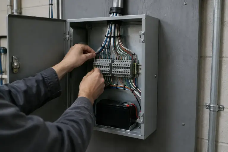
Once your cables are successfully routed from the server room to the camera locations, they must be terminated. Terminating your own bulk cable is highly recommended over using pre-made patch cords because it allows you to cut the cable to the exact length required, eliminating messy coils of slack and ensuring a highly professional finish.
To get started, you will need a few essential tools:
- A high-quality RJ45 crimping tool
- A cable stripper/scorer
- Standard RJ45 connectors (ideally pass-through style for easier alignment)
- Snips or scissors
Step-by-Step Guide to IP Camera Wiring and Termination
To ensure high-speed digital data transmission, both ends of the Ethernet cable must be terminated using the industry-standard T568B wiring color scheme. If the pinout is incorrect, the twisted pairs will not properly cancel out interference, resulting in packet loss or a complete failure to connect.
Here is the exact step-by-step process for terminating your cables:
- Strip the jacket: Use your cable stripper to score and remove approximately 1 inch of the outer plastic jacket, being careful not to nick the internal copper wires.
- Untwist and organize: Untwist the four pairs and arrange the eight individual wires in a flat, parallel line from left to right according to the T568B standard.
- Align the colors: The T568B color code sequence is:
- Pin 1: White/Orange
- Pin 2: Orange
- Pin 3: White/Green
- Pin 4: Blue
- Pin 5: White/Blue
- Pin 6: Green
- Pin 7: White/Brown
- Pin 8: Brown
- Trim and insert: Hold the wires firmly, trim them in a perfectly straight line so they are about half an inch long, and slide them into the RJ45 connector. Ensure the outer jacket of the cable sits securely inside the back of the connector for proper strain relief.
- Crimp: Insert the connector into your crimping tool and squeeze the handle firmly to press the gold pins into the copper conductors.
For more tips on perfecting your wiring technique, read our comprehensive guide on Ethernet Cable Wiring.
Testing and Troubleshooting Your Connections
Before mounting your camera and mounting brackets, you must verify that your newly terminated cable is fully functional.
A basic continuity tester is the first line of defense. By plugging both ends of the cable into the tester, you can verify that electrical signals travel successfully across all eight pins. However, keep in mind that a simple continuity tester only checks for electrical connection; it does not test data throughput. If you did not follow the T568B standard correctly, the cable might pass a continuity test but still fail to transmit video due to heavy crosstalk and signal attenuation.
For high-resolution IP cameras, using a advanced tester to measure packet loss and bandwidth capacity is highly recommended. To learn how to properly verify your network lines, check out our guide on How to Test Network Cable.
Upgrading Legacy Systems: Using Coaxial Cable for IP Cameras
Many older commercial buildings in Boston, Marlborough, and Worcester, MA, already have extensive coaxial cabling networks left over from legacy analog CCTV systems. Ripping out hundreds of feet of RG59 siamese coax cable to run new Ethernet lines can be incredibly labor-intensive and expensive.
Fortunately, you do not have to replace the legacy wiring to upgrade to modern IP cameras. By utilizing Ethernet-over-Coax (EoC) converters, you can transmit digital IP video and PoE power over existing coaxial cables.
EoC adapters work in pairs: one adapter connects to your network switch, converts the Ethernet signal to run over the coax line, and the second adapter at the camera end converts it back to an RJ45 connection. This allows businesses to seamlessly upgrade to high-definition IP cameras while saving significantly on labor and material costs. For professional assistance with legacy upgrades, explore our CCTV CATV Installation Services.
Frequently Asked Questions about Surveillance Cabling
What is the maximum cable length for PoE IP cameras?
The maximum standard distance for copper Ethernet cabling (Cat5e, Cat6, and Cat6a) is 100 meters, or approximately 328 feet. Beyond this distance, electrical resistance increases, resulting in voltage drops and packet loss that will cause the camera to drop offline.
If you need to run a camera further than 328 feet, you can install a PoE extender or active PoE switch midway to boost the signal for another 328 feet. Alternatively, some specialized commercial camera lines feature extended transmission modes that can push data up to 750 feet at reduced bandwidth.
Can I use existing coaxial cable for modern IP cameras?
Yes, absolutely. By using Ethernet-over-Coax (EoC) converters, you can easily run modern digital IP cameras over legacy RG59 coaxial lines. This is a highly effective way to upgrade your security capabilities to 4K resolution without the disruption and cost of a full building rewiring.
Why does my IP camera fail to connect even if the cable tester shows continuity?
This is a common issue for DIY installers. A basic cable tester only checks if electrical current can travel from one end of the wire to the other. It does not measure data performance.
If the T568B standard color code was not followed strictly, the twisted pairs inside the cable will not properly cancel out electromagnetic interference. At high data speeds, this causes extreme crosstalk and packet loss, preventing the camera from establishing a stable network handshake even though the wire technically has electrical continuity.
Conclusion
Properly planning, routing, and terminating your IP camera wiring is the single most important step in securing your business with a reliable surveillance system. While basic runs can be handled with the right tools, commercial properties often present complex challenges, from strict plenum fire codes to long outdoor runs requiring lightning surge protection and heavy-duty grounding.
At AccuTech Communications, we have been providing top-tier network cabling and CCTV wiring across Massachusetts, New Hampshire, and Rhode Island since 1993. Whether you need a brand-new structured cabling system or want to upgrade a legacy analog setup, our team delivers reliable, high-quality service at highly competitive pricing.
Ready to secure your facility with professional, worry-free installation? Request an Estimate with us today, and let our experts design a structured cabling system built to last.